


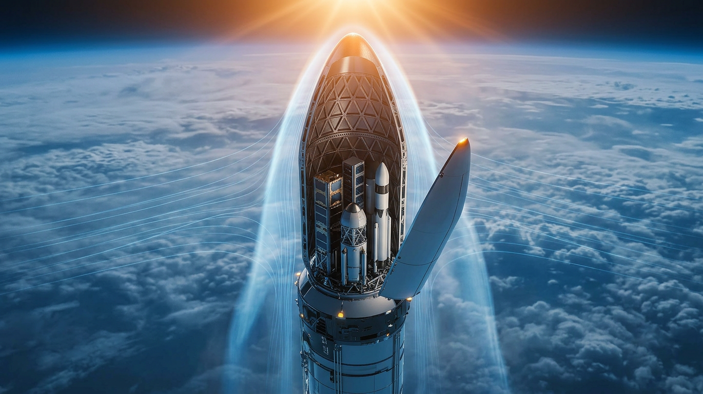

The payload fairing is the first surface the atmosphere sees and the last major structure the vehicle carries before payload separation.
It protects the satellite or spacecraft from aerodynamic pressure, acoustic loading, and thermal heating during ascent. It determines the aerodynamic drag profile of the vehicle from liftoff through max-Q. It must separate cleanly at altitude without imparting disturbance forces on the payload. And when it is jettisoned, its mass is gone so every kilogram of fairing structure that was not strictly necessary was burned for no mission benefit.
The tension is real and unavoidable. A fairing optimized purely for aerodynamic drag reduction tends to be long and slender which increases structural mass, raises acoustic amplification inside the cavity, and complicates separation dynamics. A fairing optimized purely for structural efficiency tends to be shorter and blunter which increases drag during the critical max-Q phase and reduces the internal volume available for the payload.
The globally optimal fairing satisfies all of these constraints simultaneously. Classical optimization tools cannot find it. BQP's hybrid quantum-classical platform can.
The Multi-Constraint Reality of Fairing Design
Payload fairing design is not an aerodynamics problem with structural checks. It is a fully coupled multi-physics problem where every geometric variable affects aerodynamic performance, structural mass, acoustic environment, and separation dynamics together.
Aerodynamic Drag Across the Full Ascent Envelope
The fairing operates across a wide Mach range subsonic at liftoff, transonic through max-Q, supersonic through fairing jettison altitude. The geometry that minimizes drag at subsonic conditions is not the geometry that minimizes drag at transonic conditions, where wave drag dominates and the nose fineness ratio becomes the controlling variable. A fairing optimized at a single Mach number produces sub-optimal drag across the rest of the ascent trajectory.
The correct formulation is a multi-point aerodynamic optimization across the full Mach range simultaneously minimizing the integrated drag contribution across the ascent profile, weighted by dynamic pressure. This is a high-dimensional continuous optimization problem that classical gradient methods solve poorly because the drag landscape is non-convex across Mach numbers.
Structural Mass Under Combined Loading
The fairing shell carries axial compression from vehicle thrust, bending moments from aerodynamic side loads during max-Q, internal acoustic pressure from the launch environment, and thermal loads from aerodynamic heating at high Mach numbers. The shell geometry nose ogive radius, cylinder diameter, shoulder transition geometry, and aft skirt taper determines the load path through the structure and sets the required wall thickness distribution.
Reducing shell thickness saves mass but reduces buckling margin under axial compression. Changing the nose fineness ratio improves drag but alters the bending moment distribution under aerodynamic side loads. Every geometric change that improves one structural metric affects at least two others, the hallmark of a coupled problem that sequential optimization cannot solve correctly.
Internal Acoustic Environment
The acoustic environment inside the fairing during launch is one of the most severe loading conditions the payload experiences. Sound pressure levels during liftoff and max-Q can exceed 140 dB sufficient to damage sensitive spacecraft components if the fairing geometry amplifies rather than attenuates the acoustic field.
Fairing geometry affects internal acoustic modes directly. The length-to-diameter ratio sets the fundamental acoustic resonance frequencies. Shell stiffener placement determines which structural modes couple with acoustic modes.
A fairing geometry optimized for aerodynamic efficiency and structural mass without accounting for internal acoustics may produce a cavity that amplifies specific frequency bands directly into the payload's sensitive frequency range.
Separation Dynamics and Payload Clearance
Fairing halves must separate cleanly at altitude, hinging or translating away from the payload without contact. The separation dynamics depend on fairing geometry, hinge mechanism placement, and the aerodynamic forces acting on the fairing halves during separation. A nose geometry that is aerodynamically efficient during ascent may produce asymmetric aerodynamic forces during separation that risk payload contact.
This is where classical optimization frameworks consistently fail. Each discipline of aerodynamics, structures, acoustics, separation is solved in sequence by a different specialist using a different tool. The interactions between disciplines are captured only approximately, through conservative design margins that add mass without physical justification. The result is a fairing that satisfies each discipline individually but is nowhere near the globally optimal solution across all four simultaneously.
This is precisely the class of problems described under quantum optimization problems in engineering, high-dimensional, multi-constraint, with coupling between disciplines that makes classical sequential search fundamentally inefficient.
How BQP's QIO Solver Navigates the Fairing Design Space
BQP's Quantum-Inspired Optimization (QIO) solver addresses the fairing design problem by searching the coupled multi-physics design space more completely than any classical method can within a real program budget.
Why Classical Methods Stall on Fairing Optimization
Genetic algorithms approach multi-physics design problems by evaluating populations of candidate geometries across generations. On moderate-dimensional problems with smooth fitness landscapes, they work adequately. Fairing optimization is neither moderate-dimensional nor smooth.
The design variables include nose fineness ratio, ogive profile coefficients, cylinder length-to-diameter ratio, shoulder transition geometry, aft skirt taper angle, shell wall thickness distribution, stiffener placement, and acoustic treatment configuration simultaneously. The fitness landscape across this space is non-convex, with multiple local optima corresponding to locally good aerodynamic solutions that fail structural or acoustic constraints, and vice versa. A genetic algorithm's population converges on the first local optimum it finds and stalls there.
QIO uses quantum-tunneling-inspired search mechanics to pass through the fitness barriers that trap classical populations continuing to search toward the globally optimal fairing geometry across the full coupled constraint set. On standard engineering benchmarks, QIO converges in up to 20× fewer evaluations than genetic algorithms.
For fairing optimization where each evaluation requires a CFD solve, a structural FEA run, and an acoustic analysis, this reduction in required evaluations directly determines the ROI of quantum optimization for fairing development programs.
Multi-Point Aerodynamic Optimization Across the Ascent Mach Range
The BQPhy® Optimization Solver handles multi-point optimization natively. Aerodynamic drag objectives at subsonic, transonic, and supersonic conditions can be included simultaneously in the optimization formulation weighted by the dynamic pressure at each Mach number to reflect actual mission impact. QIO finds the fairing geometry that minimizes integrated drag across the full ascent profile, not the geometry that minimizes drag at any single operating point.
This multi-point capability is what separates quantum-inspired optimization from single-point CFD-driven shape optimization, which produces locally optimal geometries that underperform across the rest of the operating envelope.
Simultaneous Structural, Acoustic, and Separation Constraints
All four constraint sets structural margins under combined loading, internal acoustic environment targets, separation clearance requirements, and manufacturing constraints are formulated as hard constraints in the QIO problem. The solver only accepts solutions that satisfy all four simultaneously. The output is not an approximately feasible fairing geometry. It is a provably feasible geometry across all four disciplines.
Engineers then receive the full Pareto front across the primary trade objectives aerodynamic drag, structural mass, and internal acoustic level rather than a single point solution. The trade between a 3% drag reduction and a 2% mass increase is visible and quantified. Design decisions are made with complete information.
Three Fairing Design Challenges BQPhy® Solves Simultaneously
Nose Ogive Profile Optimization for Transonic Drag
The nose ogive profile is the single highest-impact geometric variable for transonic drag. At transonic conditions, wave drag dominates and the pressure coefficient distribution over the nose determines the shock formation pattern. The optimal ogive profile the one that minimizes wave drag across the transonic Mach range while satisfying nose tip structural requirements and internal volume constraints is not findable by gradient descent from a standard starting geometry because the drag landscape is non-convex in the profile coefficient space.
QIO searches the full ogive profile coefficient space simultaneously, finding nose geometries that reduce transonic wave drag while satisfying the structural and volume constraints that gradient methods trade away in their descent toward the nearest local minimum.
Shoulder Transition Geometry for Flow Attachment
The transition between the nose ogive and the cylindrical fairing body is a known source of flow separation at high angles of attack during max-Q. Separation at the shoulder produces a sharp increase in pressure drag and introduces asymmetric side forces that increase structural loads. The shoulder geometry that minimizes separation risk across the angle-of-attack range encountered during ascent must simultaneously satisfy the internal volume requirement at the transition where the payload adapter interface typically sits.
This is a multi-point, multi-constraint geometric optimization problem. BQPhy handles it in a unified formulation simultaneously optimizing shoulder transition geometry for flow attachment across the angle-of-attack range while maintaining the internal volume and structural requirements at the transition zone.
Acoustic Treatment Configuration for Payload Protection
Acoustic treatment foam blankets, Helmholtz resonator arrays, or tuned mass dampers reduces internal sound pressure levels at specific frequency bands. The treatment configuration that provides adequate attenuation at the payload's sensitive frequencies while adding minimum mass depends on the fairing cavity's acoustic mode shapes which depend on fairing geometry. Geometry and acoustic treatment are coupled: changing the fairing length changes the acoustic modes, which changes the required treatment configuration.
BQPhy® solves the fairing geometry and acoustic treatment configuration simultaneously, finding the combination that protects the payload at minimum total mass addition. This is the kind of design optimization in engineering problems where treating disciplines as decoupled optimizing geometry first, then adding acoustic treatment as an afterthought consistently produces heavier, less efficient designs than solving them together.
Integration Into Your Existing Fairing Design Workflow
BQPhy® integrates as an optimization layer above your existing simulation tools. Your CFD solver, structural FEA code, and acoustic analysis tools remain exactly as they are. The QIO optimizer decides which fairing geometry candidates to evaluate, calls your existing tools to evaluate them, and generates the next set of candidates based on the results.
Integration Paths
MATLAB Integration for teams whose aerodynamic, structural, and acoustic models are MATLAB-based or MATLAB-orchestrated.
Python SDK for teams running Python-orchestrated multi-physics pipelines connecting CFD, FEA, and acoustic solvers.
REST APIs for enterprise environments integrating BQPhy® into a broader simulation orchestration platform.
The only component that changes is the optimizer. Meshing, physics modeling, and post-processing stay in your current stack. Integration is week-scale.
The Program-Level Case for Better Fairing Optimization
Fairing drag during max-Q is one of the largest single contributors to ascent trajectory gravity losses. A fairing that is 5% higher drag than necessary during max-Q requires additional propellant to maintain the trajectory propellant that cannot be used to deliver payload to orbit. Across a launch manifest of 20 to 40 flights, the accumulated payload performance impact of a sub-optimal fairing geometry is significant and entirely recoverable at the design stage.
The compounding effect of fairing mass is equally significant. The fairing is carried to jettison altitude typically 110 to 120 km before separation. Every kilogram of fairing mass that was not structurally necessary was propellant burned through the full ascent trajectory. The mass savings from a better-optimized fairing directly increase the net payload mass fraction available for the mission.
The aerospace optimization techniques that enable this level of fairing design fidelity are not future capabilities. They are available now, on current HPC, through BQP's QIO solver. The programs adopting quantum-inspired optimization for aerospace and defense at the preliminary design stage are capturing this advantage before their geometry is frozen.
Ready to test BQPhy® on your payload fairing design problem?
BQP offers a commitment-free Proof of Concept on your actual fairing geometry and constraint set. The output is a concrete optimization result on your engineering problem not a generic benchmark that gives your team the data needed to evaluate BQPhy® against your current approach.
Schedule a no-obligation Proof of Concept →
Frequently Asked Questions
Why is multi-point aerodynamic optimization important for fairing design specifically?
A fairing operates across subsonic, transonic, and supersonic conditions during a single ascent. The geometry that minimizes drag at each Mach number is different particularly at transonic conditions where wave drag dominates. Single-point optimization produces a fairing that performs well at one Mach number and sub-optimally across the rest of the ascent. Multi-point optimization, which BQPhy handles natively, finds the geometry that minimizes integrated drag across the full ascent profile weighted by dynamic pressure, the metric that actually determines mission performance.
Can BQPhy® optimize fairing geometry and internal acoustic treatment configuration in the same run?
Yes. BQPhy® QIO handles coupled problems where both the fairing geometry and the acoustic treatment configuration are design variables simultaneously. Acoustic constraints target sound pressure level attenuation at specified frequency bands are formulated as hard constraints applied across the full coupled problem. The output is the fairing geometry and treatment configuration that satisfies acoustic protection requirements at minimum total mass.
How does BQPhy® handle the separation dynamics constraint?
Separation clearance requirements minimum distance between fairing halves and payload during separation across the range of separation conditions are formulated as hard constraints in the QIO optimization problem. Fairing geometries that produce aerodynamic forces during separation that risk payload contact are excluded from the feasible solution set. The optimizer finds the best aerodynamic and structural solution within the separation-safe geometry space.
Does BQPhy® work with our existing CFD solver for aerodynamic analysis?
Yes. BQPhy® integrates as an optimization layer above your existing CFD solver whether that is OpenFOAM, Fluent, Cart3D, or an in-house Euler or Navier-Stokes code. Your CFD solver remains the aerodynamic evaluator. BQPhy® replaces only the optimizer that selects which geometry candidates your CFD solver evaluates next, through the Python SDK or REST APIs.
At what design stage does fairing optimization with BQPhy® deliver the most value?
The highest leverage is at preliminary design, when the fundamental fairing architecture nose profile family, length-to-diameter ratio, and shoulder geometry is being selected. These decisions set the aerodynamic and structural performance envelope for the entire program. Detailed design optimization of wall thickness distribution, stiffener layout, and acoustic treatment can also be supported, but the geometry-level decisions at preliminary design have the largest compounding impact on mission performance.
What is the compute cost difference compared to running genetic algorithms on the same fairing optimization problem?
QIO requires 5× to 20× fewer physics evaluations than genetic algorithms to reach equivalent or better solution quality. For a fairing problem where each evaluation requires a CFD solve, a structural FEA run, and an acoustic analysis, this translates directly to 5× to 20× less HPC wall-clock time and cost on your existing infrastructure, without any hardware changes.
.png)
.png)

%20(1).jpeg)

.svg)
.svg)
.svg)
.svg)